vdefg

vdefg
ed

fsetrse

fsetrse
grestgre

brdt

brdt
htr
Hiển thị các bài đăng có nhãn Tablets. Hiển thị tất cả bài đăng

Samsung Galaxy Tab 2 10.1 – Disassembling – How to replace the mothers board

The plastic opening tool may break during this step. You may need to use the heavy duty spudger instead.
Insert the plastic opening tool between the glass screen and the back cover so the curved end of the plastic opening tool is under the glass. Gently pry the back cover away from the glass screen.
Continue inserting the plastic opening tool around the whole device screen to completely separate the back cover from the glass screen.
Gently lift the screen up with your finger.
Using your fingers, remove the green tape covering the battery connector.
Insert the flat end of the heavy-duty spudger between the wires and underneath the battery connector. Carefully lift the black battery connector up to disconnect it from the motherboard.
The metal spudger shown in the photo is not recommended due to the possibility of an electrical short. Use an ESD-safe tool, such as a heavy-duty (nylon) spudger.
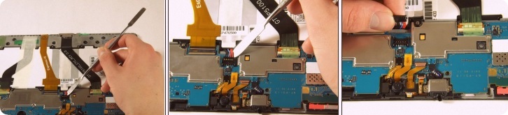
Gently lift the camera from its socket with the flat end of the heavy-duty spudger.
Gently lift the gold cable connector with the flat end of the heavy-duty spudger to disconnect it from the device.
The charging port cable is the black cable connected to the charger port. Using your fingers, peel the green tape off of the charging port cable connector.
Using the flat end of heavy-duty spudger, carefully lift the black tab that holds the charger port cable in place.
Slide the cable out.
There is a small strip of adhesive holding the charger port cable to the battery. You may need to slide the heavy-duty spudger between the cable and the battery to slide the cable out.
Use the Phillips 000 screwdriver to unscrew the two 3mm screws holding the charger port in place.
Use the flat end of the heavy-duty spudger to lift the white microphone piece until it is removed from itssocket.
Be sure to insert the spudger underneath the charger port and not inside the charger port to avoid damaging the component
Slide the flat end of the heavy-duty spudger under the charger port.
Make sure the spudger is all the way to the back of the cavity and slide horizontally across the bottom to break the adhesive.
Lift the charger port with the flat end of the heavy-duty spudger and remove it from the device.
Using your fingers, remove the green tape holding the three ribbon cables down.
Using the flat end of the heavy-duty spudger, carefully lift the black tab that holds the leftmost, black ribbon cable in place. Repeat this step for the gold ribbon cable and the black ribbon cable.
Using your fingers, gently slide each of the three cables straight out of the connectors.
Using a Phillips #000 screwdriver, remove the ten 3mm screws that hold the battery down.
Lift the battery with your hands and remove it from the device.
Using the flat end of the heavy-duty spudger, lift up the black ribbon lock directly left of the headphone jack from the black side.
After lifting up the lock, insert the heavy-duty spudger underneath the gold ribbon and slide to disconnect the gold ribbon.
The rear camera may pop out.
Using the flat end of the heavy-duty spudger, gently lift up the ribbon lock directly above the one in the previous step from the brown side.
After lifting up the lock, remove the gold ribbon with the heavy-duty spudger as you did in the previous step.
Use the flat end of the heavy-duty spudger to pop off and disconnect all the marked connectors attached to the motherboard.
After disconnecting all of the connectors, push up on the motherboard with your thumbs to dislodge it from the tabs fastening the bottom of the motherboard. Then lift up the motherboard tocarefully remove it from the device.
You may need to repeat this step a few times. The motherboard can be difficult to remove.

Orbo Jr. – Disassembling procedure – How to remove Motherboard – Tablets repair and service

Category: Tablets Repair and Service 

Contents of this article 

  • How to remove the case 
  • How to remove the battery 
  • How to remove the mother board 

Orbo Jr. Tablet

Use your thumbs to gently pry the silicon case away from the tablet starting at one of the corners. Once the first corner is separated the other three corners should slip off easily.
Use the plastic opening tool to pry the back off the tablet. Work your way around the edges. Once you have one side open you can slowly unsnap the rest of the case and use the tool as needed.
Go slowly when you pry the back off to ensure you do not crack the case or damage the screen.
Gently pull the cables attached to the speaker to remove it from the back cover.
The speaker is taped in the back cover and caution should be used when pulling on the wires.
Pull back the tape to expose the wires that are attached to the battery.
Do not attempt to fully remove the battery. It is still connected to the motherboard by two wires.
Use a nylon spudger to lift the battery from the right side of the device. Slowly remove the adhesive below the battery.
To avoid damage to device and battery, do not attempt to remove the battery until adhesive is completely detached.
Desolder the battery wires from the positive and negative connection to the motherboard
Be careful to not make contact to other components on the motherboard while using the soldering iron
Unsolder the positive and negative speaker wires from the connection on the motherboard.
Positive and Negative battery terminals.
Be careful to not make contact to other components on the motherboard while using the solder iron.
Use the pointed end of a spudger to flip up the black tab connecting the camera's ribbon cable to the motherboard.
Pull lightly on the ribbon to remove the camera ribbon from the tab.
Unsolder the Wifi wire from the connection on the motherboard.
Be careful to not make contact to other components on the motherboard while using the solder iron.
Unsolder the display wires from the connection on the motherboard.
Be careful to not make contact to other components on the motherboard while using the solder iron.
Use the flat end of the spudger to lift and remove the black tape covering the ribbon connection tab.
The tape should be removed slowly.
Using the tip end of the spudger, slide back the black clips on the side of the right ribbon connection.
Gently pull the display ribbons to remove them from the motherboard connections.
Repeat the same steps for the left ribbon connection.
Remove the following Phillips #000 screws securing the motherboard and remove it.

Fire HD 8 – Disassembling procedure – Tablets repair and service

Heat the edges of the screen with a heat gun on the lowest setting by using sweeping motions.
Make sure you use sweeping motions with the heat gun, instead of hovering over one area.
After 1-2 minutes, use a plastic opening tool to pry the screen loose. Start at the top right corner and gently pry the screen from the device.
Be careful not to bend the screen by pushing it too far from the rest of the device.
Slide a plastic opening tool and spudger along the underside of the screen using enough force to peel the screen and the adhesive strip from the other half of the device.
Be mindful of the orange cable connecting the screen to the mid-bottom of the device.
To remove the screen from the device, use tweezers to gently pull the orange cable from its connection to the screen.
Using tweezers, carefully lift the copper strip from the right side of the speaker.
Remove the two screws located on the top left and bottom right of the speaker using a T4 screwdriver.
Lift the right side of the speaker and carefully unhook and remove it from the device.
Be mindful of the white wire connecting the speaker to the device.
Set aside the black speaker and follow the white wire to its connection on the upper left side of the motherboard.
Using tweezers, gently pry the black clip upward from the board.

Magellan RoadMate 1440 – Disassembling procedure – How to replace the mother board

Place the RoadMate with the screen facing down.
Locate the four screws in the back cover of the device. Use a Phillips #0 screwdriver to remove all four 4.2mm Phillips #0 screws.
Locate the screws at the bottom of the device. Use a Phillips #0 screwdriver to remove the two 4.2mm Phillips #0 screws.
Insert the black spudger into the crease in the side of the RoadMate.
Move the end of the spudger down to break the seal between the two plastic shells.
Continue doing this along each side of the RoadMate to ensure a smooth removal.
Fully separate the two sides of the case.
Locate the tape on the battery wires and the tape on the speaker wires. Remove both pieces of tape.
Use the black spudger to break the seal between the adhesive and battery. Use the same spudger to continue to pry the battery from the backing
This may be a little tough to separate the battery and the adhesive
Lift the battery from the device
Once the battery is free from the adhesive, remove the piece of tape with a pair of tweezers that is covering the connection of the battery to the motherboard.
Unplug the battery from the mother board by pulling back the clips and pulling the wires away from the motherboards receptacle
It is important for your and the device's safety to remove the battery before continuing with any other part removals.
It is not necessary to separate the red and white wires from the battery. A replacement battery pack will come with similar wires already attached.
After the back has been removed, locate each of the screws securing the speaker to the inside of the back cover.
Use a Phillips #0 screwdriver to remove the two 3.8mm Phillips #0 screws.
The speaker is connected to the motherboard by a few wires Gently remove the connector from the motherboard to completely remove the speaker.
Once the back cover has been removed, lift the power switch from the device.
This is only a sliding switch, the button to power the device on is inside the unit
Remove the device's screen.
It may be necessary to get help from a friend to hold the device stable while removing the screen.
Using two hands, pull back the tabs holding the screen in place.
Use a spudger to help use leverage to remove the screen, if necessary
Raise the switch locking the ribbon cable in place.
Using twesers, pull the ribbon cable from the socket.
With the ribbon cable removed, the screen is completely disconnected from the device.
To replace the ribbon cable, press the two tabs to push the head into the socket.
Now that the screen has been removed from the motherboard, the motherboard is not connected to anything on the device. Slide the ribbon cable through the opening in the circuit board in order to separate the two.