vdefg

vdefg
ed

fsetrse

fsetrse
grestgre

brdt

brdt
htr

Sony Xperia M4 Aqua – Disassembling procedure – How to replace the LCD display – Mobiles and smartphones repair and service

Place the phone face-down, and use a heat gun or hair dryer to evenly heat the back surface until to soften the adhesive.
Attach a suction cup to the back of the M4 Aqua by carefully pushing down on it near the top of the phone.
While Pulling on the suction cup, slide a thin plastic spacer (guitar picks work well) between the back cover and the phone. Slide it around the edges to break the adhesive. Be careful, but don't be afraid to use some force. You should hear a sticky breaking sound.
Remove the back cover by pulling it from the chassis. it is flexible and can be bent, be careful.
Near the bottom of the phone, unscrew the two phillips head screws, one 3 millimeters and the other 4 millimeters,
Remove the black plastic strip to reveal the speaker assembly. It is hooked underneath the circuit board beneath, force will be required to pry it out. Carefully unplug the microphone connector as you do this, ensuring not to snap it.
Remove the Metal LCD assembly cover by lifting up and pulling it out away from the edge of the phone, towards the middle. Disconnect the LCD connector. The assembly cover is flexible and can be bent, be careful when applying force. Carefully unstick the connector from underneath the LCD cover
Removing the screen is similar to how the back cover is removed.
Apply heat evenly to the screen attach a suction cup near the top of the phone, and use a plastic spacer to break the adhesive seal between the screen and the phone housing. Twisting the spacer can help to separate the back plate from the chassis.
Remove the screen by pulling it away from the chassis

Spirit treadmill – Spirit Z 500 – How to calibrate the treadmill – How to access Engineering mode – Treadmill repair and service


Checking treadmill circuit breaker
1. The circuit breaker is a small, red button between the power cord and the power switch.
2. Press the button in to reset.
Check roller for magnet
1. The front roller should have a round magnet and a round counter weight.
2. Take a screw or something metallic and test each one.
3. Only one should be magnetic.
Adjust Torque Boost

1. Using a small screw driver, turn the dial counter clockwise until it stops.
2 Press the START button on the console.
3. With someone standing on the walking belt, turn clockwise until the belt begins to move.
4. Increase the speed and check for smooth belt movement.
Replacing controller

1. Disconnect power cord from unit.
2. Remove motor hood.
3. Remove two Phillips screws holding in the controller.
4. Disconnect all wires connected to the controller.
5. Insert new controller, secure with Phillips screws.
6. Reconnect wires to controller. 
Replacing wire harness

1. Turn power switch off.
2. Unplug harness from console and controller.
3. Tie the end of the new harness to the old harness (with a zip-tie or spare wire).
4. As you pull the old harness out of the upright, you will pull the new harness in.
5. Connect to board and console, & turn power back on.
Replacing drive motor

1. Turn power switch off.
2. Disconnect red and black motor wires from controller.
3. Loosen tension bolt and remove four motor bolts.
4. Take off drive belt.
5. Insert new motor into place.
6. Put drive belt on.
7. Put in four motor bolts. Do not tighten them all the way down.
8. Tighten the tension bolt until you only have about an inch of play in the drive belt.
9. Tighten down the four motor bolts.
10. Plug the motor wires into the controller.
Replacing incline motor
1. Turn power switch off.
2. If possible, fold up unit.
3. Turn treadmill onto its side.
4. Disconnect motor wires from controller.
5. Remove bolt from incline tube.
6. Remove bolt from top of incline motor and take out motor.
7. Insert new motor and put in bolt on the top.
8. Reconnect motor wires to controller.
9. Turn on unit. The new motor should turn until it is at “zero”.
10. Insert bolt into incline tube.
Engineering mode
1. Remove the tether cord.
2. Press and hold the START, ENTER, and STOP buttons and replaced the tether
cord.
3. The display will say ENGINEERING MODE. Press ENTER.
4. Press the UP and DOWN buttons to scroll through the sub menus:
5. Press ENTER to access the desired program.
Calibration : Speed Calibration – In this mode, you can test the speed.
Incline Calibration – In this mode, you can test the incline.
Factory Settings: This mode will allow you to view the Wheel size, Max inc, Max and Min speed.
Use the UP and DOWN buttons to scroll through.
Security: Child Lock On/Off
Press ENTER to turn on or off. To unlock display, press START and ENTER.
Functions: Sleep Mode On/Off. Press ENTER to turn on or off.
Units English/Metric. Press ENTER to change.
Maintenance
Lube Message Reset. Press ENTER to reset.
Odometer Reset. Press ENTER to reset.
Pause Mode On/Off. Press ENTER to turn on or off.
Display Test: Test all LED’s
Key Test: Test all buttons on console.

Calibrating the unit
1. Remove tether cord.
2. Press and hold the START and FAST buttons. Replace the tether cord while maintaining the buttons. Display will show “FACTORY SETTING”. Press ENTER.

3. Units English / Metric. Press UP or DOWN to change. Press ENTER.
4. Adjust wheel diameter using UP or DOWN. Should be 2.75. Press ENTER.
5. Adjust minimum speed to 0.5 using UP and DOWN. Press ENTER.
6. Adjust maximum speed to 12 using UP and DOWN. Press ENTER.
7. Adjust maximum elevation to 15 using UP and DOWN.
8. Press START to begin calibration. DO NOT STAND ON BELT DURING CALIBRATION.
Checking wire harness for continuity
1. Set your multimeter to read ohms.
2. Place the test leads at opposite ends of the wire, make sure both leads are on the same wire and are in contact with metal.
3. If the reading is close to 0 ohms, the wire has continuity (unbroken).
4. If the reading is very high or there is no reading at all, there is no continuity.
5. If there is no continuity, the harness needs to be replaced.
Speed sensor adjustment
1. Take off the motor hood.
2. The speed sensor is located on the frame, near where the drive belt goes around the front roller.
3. The sensor should be adjusted to about 1/16th of an inch from the front roller.

Samsung Galaxy Tab 2 10.1 – Disassembling – How to replace the mothers board

The plastic opening tool may break during this step. You may need to use the heavy duty spudger instead.
Insert the plastic opening tool between the glass screen and the back cover so the curved end of the plastic opening tool is under the glass. Gently pry the back cover away from the glass screen.
Continue inserting the plastic opening tool around the whole device screen to completely separate the back cover from the glass screen.
Gently lift the screen up with your finger.
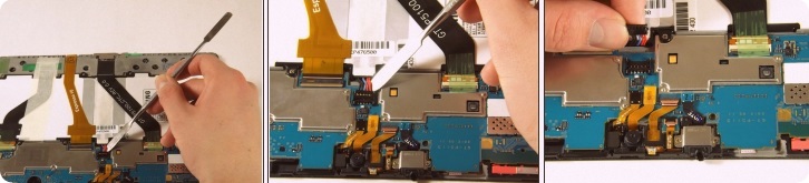
Using your fingers, remove the green tape covering the battery connector.
Insert the flat end of the heavy-duty spudger between the wires and underneath the battery connector. Carefully lift the black battery connector up to disconnect it from the motherboard.
The metal spudger shown in the photo is not recommended due to the possibility of an electrical short. Use an ESD-safe tool, such as a heavy-duty (nylon) spudger.
Gently lift the camera from its socket with the flat end of the heavy-duty spudger.
Gently lift the gold cable connector with the flat end of the heavy-duty spudger to disconnect it from the device.
The charging port cable is the black cable connected to the charger port. Using your fingers, peel the green tape off of the charging port cable connector.
Using the flat end of heavy-duty spudger, carefully lift the black tab that holds the charger port cable in place.
Slide the cable out.
There is a small strip of adhesive holding the charger port cable to the battery. You may need to slide the heavy-duty spudger between the cable and the battery to slide the cable out.
Use the Phillips 000 screwdriver to unscrew the two 3mm screws holding the charger port in place.
Use the flat end of the heavy-duty spudger to lift the white microphone piece until it is removed from itssocket.
Be sure to insert the spudger underneath the charger port and not inside the charger port to avoid damaging the component
Slide the flat end of the heavy-duty spudger under the charger port.
Make sure the spudger is all the way to the back of the cavity and slide horizontally across the bottom to break the adhesive.
Lift the charger port with the flat end of the heavy-duty spudger and remove it from the device.
Using your fingers, remove the green tape holding the three ribbon cables down.
Using the flat end of the heavy-duty spudger, carefully lift the black tab that holds the leftmost, black ribbon cable in place. Repeat this step for the gold ribbon cable and the black ribbon cable.
Using your fingers, gently slide each of the three cables straight out of the connectors.
Using a Phillips #000 screwdriver, remove the ten 3mm screws that hold the battery down.
Lift the battery with your hands and remove it from the device.
Using the flat end of the heavy-duty spudger, lift up the black ribbon lock directly left of the headphone jack from the black side.
After lifting up the lock, insert the heavy-duty spudger underneath the gold ribbon and slide to disconnect the gold ribbon.
The rear camera may pop out.
Using the flat end of the heavy-duty spudger, gently lift up the ribbon lock directly above the one in the previous step from the brown side.
After lifting up the lock, remove the gold ribbon with the heavy-duty spudger as you did in the previous step.
Use the flat end of the heavy-duty spudger to pop off and disconnect all the marked connectors attached to the motherboard.
After disconnecting all of the connectors, push up on the motherboard with your thumbs to dislodge it from the tabs fastening the bottom of the motherboard. Then lift up the motherboard tocarefully remove it from the device.
You may need to repeat this step a few times. The motherboard can be difficult to remove.

Nexus 5X – Disassembling – How to replace the battery

Insert a SIM card ejection tool into the SIM card slot located on the left edge of the phone.
Press in with the tool of your choice until it pops out of the side of the phone.
Remove the SIM card slot tray and set aside.
Starting at the SIM card slot, stick the plastic opening tool in between the back panel and the phone.
Slide the opener tool gently around the phone until you hear clicks and visibly see the panel separate from the body of the phone.
Continue this process on each edge of the phone, until the only thing holding the back panel to the body of the phone is the fingerprint scanner.
Gently detach the back panel from the finger print scanner on the back of the phone.
Remove the ten screws securing the middle frame using a Phillips #000 bit piece.
Starting from the bottom, use a plastic opening tool to pry off the middle panel from the phone.Be careful when doing this because the middle panel comes in two pieces and if you start at the top, you may break the connectionbetween the two pieces.
Using a plastic opening tool or fingernail, gently pry up the battery cable connector to release it from the motherboard.
Using an Opener, or something similar, heat the phone so the adhesive will loosen.
Carefully insert a single flat nylon spudger underneath the battery.
Apply enough pressure to release the battery from the adhesive holding it to the phone.
Removed the motherboard completely before attempting to remove the battery due to the
adhesive on our device being too strong and we did not want to damage the motherboard. similar to use.
Be extremely careful when doing this, if you use something sharp you may pierce the battery.

Canon EOS 5D Mark II – Disassembling procedure – How to replace the LCD display

Lift the rubber flap covering the input/output jacks.
Using a Phillips #0, remove the single 3.4 mm screw.
This step will permanently erase all user settings.
The memory battery can now be easily slid out of place.
Peel back the rubber cover above the in/out ports to reveal two screwheads.
Remove both 5.4 mm screws using a Phillips #0.
Lift the in/out port plastic covering from the bottom where the backupbattery used to be.
Remove each 6.3 mm screw on either side of the viewfinder using a Phillips #0 screwdriver.
Remove the three 4.8 mm screws on the bottom of the back plate using a Phillips #0.
Peel back the rubber covering next to the menu dial to access thescrew.
Remove the single 3.4 mm screw using a Phillips #0.
The back panel can now fall off easily by turning the device upside down. Be sure to catch it so the data ribbons do not tear or tug.
Remove each data ribbon cable from the motherboard by applyingpressure down towards the motherboard and gently sliding your thumb upwards on the slot where the cable meets the motherboard. Thiswill raise a very small clip that locks the cable in place.
The back panel is now free from the rest of the device.
Remove each of the 3.4 mm screws holding in the LCD using a Phillips #0.
Grip the wire attaching the speaker to the data ribbon cable and pull itout.
The LCD is now free from the back panel.

Sony LCD Projection television KDF-55WF655 - KDF-60WF655 – Diagnostic indication – Led blinking and causes – Lamp hour reset – Power supply circuit

Diagnostic Test Indicators
When an error occurs, the POWER/STANDBY or LAMP LED will flash a set number of times to indicate the possible cause of the problem. If there is more than one error, the LED will identify the first of the problem areas. If the errors occur simultaneously, the one that corresponds to the fewest flashes is identified first.
Results for all of the following diagnostic items are displayed on screen. No error has occurred if the screen displays a “0”.
Diagnostic Item
Description
Number of times
STANDBY or LAMP LED
lamp flashes
Probable Cause
Detected Symptoms
Lamp cover error
3 times
- Lamp cover is not fastened securely
- No picture/No sound
Fan error
4 times
- Fan1-4 Power is not supplied.(G2 board)
- Fan connector is not seated securely
- Fan caught wires or harnesses
- No picture/No sound
Temp error
4 times
- Internal temperature is too high
- IIC-E line connector is not seated properly
(WE:H3 board, WF/XS:H4 board)
- No picture/No sound
Lamp driver error
5 times
- Lamp driver defect
- No picture/No sound
Low B error
6 times
-No "DD 6V " output (G1 board)
- No picture/No sound
Audio error
7 times
- Short-circuit of Audio power supply line
(KD board, G1 board)
- Blowout of a fuse
(F4702,F4703,F4704 on KD board)
- IC failure
(IC4703,IC4708,IC4710 on KD board)
- No picture/No sound
D-OVP error
8 times
- Overvoltage of +3.3V or +2.5V
(A board, B board)
- No picture/No sound
ATSC-OVP error
10 times
-No "DTL MODULE 5V " output
(G1 board, G2 board)
- No picture/No sound
Lamp error
LAMP-LED is ON.
- Lamp is dead
- No picture/No sound
Releasing the POWER/STANDBY LED Flash
Unplug the power cord from the outlet to temporarily stop the POWER/STANDBY lamp from flashing.
Self-Diagnosis Screen Display
For failures that are difficult to reproduce, or accompany occasional power off and/or picture mute, the Self-Diagnosis screen display is useful to specify the cause.
To Bring Up Screen Test
In standby mode, press the buttons on the Remote Commander sequentially, in rapid succession, as shown below:
1. Display  > Channel 5 > Sound Volume - > Power ON
Clearing the Result Display
To clear the result display to “0”, press the buttons on the Remote Commander sequentially when the diagnostic screen is displayed, as shown below:
1. If the screen is already displayed, proceed to step 3. If not, Power off (Set to Standby model).
2. Press Display > Channel 5 > Sound Volume - > Power ON
3. Press Channel 8 > ENTER
Clearing the Self-Diagnostic Screen
The self diagnosis screen display is cleared by turning off the set using the Remote Commander or the power switch.
Self-Diagnosis Function Operation
Blinking
Causes
Description
3
Lamp cover
The rib at the back of the lamp cover closes the SW on the T board to ground pin 3 of CN8001.
It is monitored by the DE-micro (pin 94 of IC6902) and turns off the lamp when it is opened.
4
Fan
Fan rotation is detected by "FAN-PROT" and the DE-micro (pin 92 of IC6902) turns off the lamp
when it is "high".
4
Temp
When the temperature sensor on the H3 board (WE models) or H4 board (WF/XS models)
detects high temperature, or IIC-E line connector (CN6022:G2 board, CN44:H3board/H4board)
is not seated securely, the DE-micro turns off the lamp.
5
Lamp driver
When the "LAMP-PROT" (pin 95) is low, the lamp is not turned on. If the "LAMP-HV-DET"
(pin 96) is low at the same time, it is classified as no high voltage of the lamp driver.
6
Low B error
When no "DD 6V " is detected, pin 129 of TV-micro is low and it turns off the main power.
7
Audio
When DC voltage is detected at the speaker or woofer outputs, pin 128 of TV-micro is low and it
turns off the main power.
8
D-OVP
When overvoltage of "+3.3V" or "+2.5V" is detected, pin 126 of TV-micro is low and it turns off
the main power.
10
ATSC-OVP
When no "Digital Module 5V" is detected, pin 127 of TV-micro is low and it turns off the main
power.
LAMP
Lamp
When the "LAMP-PROT" (pin 95) is low, the lamp is not turned on. If the
"LAMP-HV-DET" (pin96) is high at the same time, it is classified as no lamp or a dead lamp.
Reading and Resetting Lamp and Panel time
Use the following to determine the lamp and panel time of a set.
Screen Display Method
In standby mode, press the buttons on the Remote Commander sequentially, in rapid succession, as shown below:
1. Press Display > Channel 5 > Sound Volume + > Power ON
2. To enter the DE-micro service menu, press Jump 3 times.
3. To display the Lamp time, press Channel [2] 9 times.
To reset the lamp time press Channel 3 > Mute > Enter .
WRI-EXE(Character color is Red) is momentarily displayed and LampTM is reset to “0”.
Exiting Service Mode
After completing the changes exit service mode by turning off the set using the Remote Commander or the power switch.

POWER SUPPLY CIRCUIT 
CLICK ON THE IMAGE TO ZOOM IN